
Greyline Feedline Kit: Ladder Line, Coax, Interface Block

Every Greyline antenna ships with a feedline kit. A short roll of 450-ohm window line, a 1:1 interface block, and the hardware to make it work with the tuner you already own. Here is the order of operations, then the engineering behind every choice.
Quick Start: The Order of Operations
Six steps. Read them once before you pick up a tool. The deep-dive reference for each step lives further down the page.
- Identify the three pieces. Lower pole section. Upper pole section. Roll of 450-ohm window line. Bag of three 3D-printed ladder-line spacers. The interface block parts and PL-259 hardware live in their own bag and come into play later.
- Park the spacers on the ladder line first. Lay the window line flat on a clean bench. Snap each spacer into an open square in the line, roughly twelve inches apart, climbing toward what will be the feedpoint end. Three spacers, evenly spaced, all on the line before anything goes near the pole.
- Thread the ladder line up through the lower pole section before you join the two sections. This is the one common-sense step that is not obvious until you've done it once. Feed the ladder line up through the bottom of the lower section so the feedpoint end emerges from the top. The spacers ride up inside as you go.
- Now fasten the upper section onto the lower. With the ladder line already living inside the lower section and trailing out the top, slide the upper section into place and secure it. Pulling line up through a fully-assembled pole is possible. Doing it this way is easier on you and easier on the line.
- Land the feedline at the feedpoint insulator. Mind the phase. Mark which conductor connects to the upper radiator. The upper half is the primary radiator in a vertical dipole — feed the upper conductor with the center conductor of your coax (or the matching side of your ladder line). It matters.
- Bring the bottom end to your tuner. If your tuner has balanced terminals or long-wire posts, land the window line directly. Fewer junctions, lower loss. If your tuner offers only an SO-239, build the interface block (instructions further down) and plug into it. Either path is valid. Your station, your call. For the system-level view of where the choke and tuner sit in the signal chain, see Feed System Configuration.
The one thing not to miss.
The ladder line — with spacers already on it — must be threaded inside the lower pole section before the upper section is fastened on. Common sense, easy to overlook the first time. If you find yourself trying to fish a spaced-out ladder line through a fully-assembled pole, stop, separate the sections at the ground insulator, and start the line from the bottom.
That is the install. Below is why every piece of the kit is the piece it is.
Where This Fits in the Larger System
The feedline kit is one chapter. The full feed system is radio → tuner → RF choke → coax → antenna (in either order — choke before or after the tuner depending on whether your tuner sits in the shack or at the base of the antenna). The diagram below shows the OCF vertical dipole and where the feedline kit lands in that chain.

For the full theory — floating balanced output, why the 1:1 current choke goes where it goes, and the two accepted signal-chain configurations — read Feed System Configuration: Tuner, Choke, and Coax Setup. This page is the install. That page is the why.
Why Ladder Line Won
For years we ran coax inside the antenna. It worked. Higher-power operators occasionally pushed it past its comfort zone. In 2018 we replaced that internal coax stub with a short run of 450-ohm window line. Lower loss. Higher efficiency. More of your signal reaching the radiator, and more of the band's whispers reaching your receiver.
Every decibel counts. On receive, a decibel can be the difference between a logged contact and a lost one. On transmit, a decibel is power you already paid for. We don't give it away.
What's in the Kit

Components and specific vendors rotate as we work with different suppliers, but the kit always does the same job: it gets the signal from the feedpoint of your antenna to the input of your tuner, with the fewest compromises we can engineer.
The interface block is a 3D-printed adapter that bridges 450-ohm window line to a PL-259 coax connector. No soldering iron required to land at the standard SO-239 on the back of your tuner. Plug and play.
Your Tuner, Your Choice
Half of our buyers run a desktop tuner in the shack. Half run a remote tuner at the base of the antenna. Both approaches are valid. Greyline does not dictate.
If your tuner has balanced antenna terminals or long-wire posts, you can connect the window line directly. Fewer junctions, fewer losses. If your tuner offers only an SO-239 jack, the interface block converts you to coax in a clean, repeatable way.
The purist and the plug-and-play operator both get what they want. No one has to compromise on signal quality.
The Spacers
Inside the pole, from ground level to feedpoint, three 3D-printed spacers keep the ladder line centered and clear of the aluminum wall. Snap each one into an open square of the window line, spaced roughly a foot apart as the line climbs.
If you forgot to add the spacers before threading the line and the pole is already standing, all is not lost. Separate the pole at the ground insulator, slide the line up to the feedpoint, dress the spacers as you go, and reassemble. Annoying. Recoverable.
Phase it right.
When you land the feedline at the feedpoint insulator, mark which wire goes to the upper radiator. Feed the upper (longer) section with the center conductor of your coax. The upper half is the primary radiator in a vertical dipole. Feed it accordingly. Makes a difference.
Interface Block Assembly, Step by Step
Parts you'll need: the 3D block adapter kit (two halves, four screws, nuts), a solder-type PL-259, and a UG-175 mini-8 reducer. The kit ships complete.

Figure 1. Completed interface — 450-ohm window line landing cleanly at a PL-259.
Prep the Window Line
Trim the window line to the dimensions shown below. Tin the wire tips lightly. On the longer conductor, strip the polyethylene insulation completely and replace it with 2.25 inches of 4 or 5 mm Teflon tubing. The Teflon handles the heat near the PL-259 and lets the assembly tolerate high power cleanly.

Solder in Order
Slide the Teflon-covered wire into the UG-175 reducer, then into the PL-259. Let the center conductor stick out past the tip pin. Do not solder the tip yet. Solder the side ports first, with the Teflon already in place. Solder the tip last. Get the order wrong and the tubing melts before the heat path is clean.

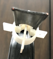
Figure 2. Shell half showing the recess that clamps the UG-175 reducer (left) and the window-line compression box (right).
Close the Shell
Seat the assembly in one shell half. Thread the PL-259 body and the UG-175 together until they clamp the shell edge firmly. Bend the wires to fit. Close the second shell half over the top. Four 1/2-inch stainless 6-32 pan-head screws draw the halves together. One side of the shell is drilled 9/64 for clearance; the other is tapped for 6-32.
Want weatherproofing? Fill the shell with RTV silicone during assembly. Skip the RTV if you want to be able to disassemble later.
A Word on Grounding
We do not ground the antenna, the remote tuner, or the RF choke while operating. Your station ground is a separate discipline — follow ARRL and FCC guidelines for station grounding and lightning protection. The feedline kit is about signal integrity. Safety grounding is about the rest of your shack.
Featured Reads
- Why Greyline — A Practical List of Benefits
- ZF2B: Verticals Louder Than a Full-Size 5-Element Yagi on 10M (Video)
- Tuner at the Base, or at the Desk? A Straight Answer.
- How Close Can You Install Near Buildings, Trees, and Your Home?
- KJ7CWQ: 16' DXF in a Phoenix HOA, 160–6M On the Air
- Ham Radio Adventure Stories — The Greyline Blog
73 Greyline — 435-200-4902
Ham Radio is fun again. Pass it on.

Smart. Strong. Elegant.