Greyline Feedline Kit: Ladder Line, Choke, and Adapter — Install Guide

Every Greyline antenna ships with a feedline kit: a short roll of 450-ohm window line, five snap-on ferrites that make the 1:1 choke, a ladder-line to PL-259 adapter, spacers, and the hardware to make it all work with the tuner you already own. Here is the order of operations, then the engineering behind every choice.
How most owners set it up — and your other options
The ladder line lives inside the pole, from the feedpoint down to the base. At the base, most owners use the adapter to join it to coax, and run the coax to a tuner — a remote tuner right at the pole, or a desktop tuner in the shack. That is the common installation, and this kit is built for it.
Common is not always most efficient. You can also run ladder line all the way to a balanced tuner on an aerial run, or bury balanced twisted pair in metallic conduit. Which loses least on your run depends on the length, the bands, and the line — so compare them in the Feedline Loss Calculator before you buy feedline. Every option is laid out on Feedline System Kits.
Read this first: no 9:1 needed
The window line says 450 ohms and your coax says 50, so it is natural to think the system needs a 9:1 (or 4:1) transformer at the adapter. It does not. The 450 ohms is the line's characteristic impedance, not the impedance your antenna presents. A multiband antenna shows a different impedance on every band, so no fixed ratio describes it and no fixed transformer can match it — a transformer only moves the mismatch around and adds loss.
Tuner for the match, choke for the common mode. Your tuner matches whatever the antenna presents, band by band. The five ferrites make the 1:1 choke that keeps RF off the outside of the feedline. The adapter is a direct connection, not a transformer. That is the whole feed system.
Quick Start: The Order of Operations
Seven steps. Read them once before you pick up a tool. The deep-dive reference for each step lives further down the page.
- Identify the pieces. Lower pole section. Upper pole section. Roll of 450-ohm window line. Bag of three ladder-line spacers. Five snap-on ferrites. The adapter parts and PL-259 hardware live in their own bag and come into play later.
- Park the spacers on the ladder line first. Lay the window line flat on a clean bench. Snap each spacer into an open square in the line, roughly twelve inches apart, climbing toward what will be the feedpoint end. All three on the line before anything goes near the pole.
- Thread the ladder line up through the lower pole section before you join the two sections. Feed it up through the bottom of the lower section so the feedpoint end emerges from the top. The spacers ride up inside as you go.
- Now fasten the upper section onto the lower. With the ladder line already inside the lower section and trailing out the top, slide the upper section into place and secure it. Pulling line up through a fully assembled pole is possible; doing it this way is easier on you and on the line.
- Land the feedline at the feedpoint insulator. Mind the phase. Mark which conductor connects to the upper radiator; that conductor goes to the center pin of the PL-259 at the other end. The upper half is the primary radiator in a vertical dipole. It matters.
- Place the choke. The five snap-on ferrites make the 1:1 choke, and any choke follows the same rule: it goes at the feedpoint — unless you run a remote tuner at the antenna, in which case it goes on the coax on the radio side of the tuner. Close each ferrite firmly until it clicks. Where the choke goes, and why →
- At the base of the pole, connect your feedline. For coax, build the adapter (instructions below) on the bottom end of the ladder line, connect your coax, and run it to your tuner — at the pole or in the shack. For ladder line all the way or buried twisted pair, see Feedline System Kits. For the system view, see Your RF System, End To End.
The one thing not to miss.
The ladder line — with spacers already on it — must be threaded inside the lower pole section before the upper section is fastened on. If you find yourself fishing a spaced-out ladder line through a fully assembled pole, stop, separate the sections at the ground insulator, and start the line from the bottom.
That is the install. Below is why every piece of the kit is the piece it is.
Where This Fits in the Larger System
The feedline kit is one chapter. With a tuner in the shack, the chain runs antenna → 1:1 choke at the feedpoint → ladder line down the pole → adapter at the base → your feedline → tuner → radio. With a remote tuner at the pole, the tuner sits at the base and the choke moves to the radio side of it. The diagram below shows the OCF vertical dipole and where the kit lands in that chain.

For every configuration — coax to the pole, ladder line to the shack, or buried balanced line — see Complete Feedline System Kits. This page is the install. That page is the why.
Why Ladder Line Inside the Pole
For years we ran coax inside the antenna. It worked, but higher-power operators occasionally pushed it past its comfort zone. In 2018 we replaced that internal coax with a short run of 450-ohm window line: lower loss at the high SWR a multiband antenna presents on most bands, right where the SWR is highest, which means more of your signal reaching the radiator and more of the band's whispers reaching your receiver.
Every decibel counts. On receive, a decibel can be the difference between a logged contact and a lost one. On transmit, a decibel is power you already paid for.
What's in the Kit

Window line, five snap-on ferrites for the 1:1 choke, three spacers, and the ladder-line to PL-259 adapter. Components evolve as we improve them, but the kit always does the same job: it gets the signal from the feedpoint down the pole to your feedline, choked, with the fewest compromises we can engineer.
The adapter bridges the window line to a PL-259 at the base of the pole, so coax connects with a standard fitting. It is a direct connection — no transformation — so the tuner sees exactly what the antenna presents and does its job.
Your Tuner, Your Choice
Some owners put a remote tuner right at the base of the pole, with the coax running from it to the shack; others run the feedline straight to a desktop tuner in the shack. Both work, and almost any decent-size tuner will do. A remote tuner at the pole has one extra advantage: the coax behind it sees a near-perfect match, so its loss is as low as it gets. Do I need an antenna tuner? walks through the choice.
Either way, no transformer goes between the ladder line and the coax. The adapter connects them; the tuner matches; the choke chokes.
The Spacers
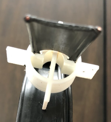
Inside the pole, from ground level to feedpoint, three spacers keep the ladder line centered and clear of the aluminum wall. Snap each one into an open square of the window line, roughly a foot apart as the line climbs.
If you forgot the spacers and the pole is already standing, all is not lost: separate the pole at the ground insulator, slide the line up to the feedpoint, dress the spacers as you go, and reassemble. Annoying. Recoverable. Spares are on the shelf: Ladder Line Spacers, 3-pack.
Phase it right.
When you land the feedline at the feedpoint insulator, mark which wire goes to the upper radiator, and carry it to the center pin of the PL-259 at the base. The upper half is the primary radiator in a vertical dipole. Feed it accordingly.
Adapter Assembly, Step by Step
Parts: the adapter shell (two halves, four screws, nuts), a solder-type PL-259, and a UG-175 mini-8 reducer. The kit ships complete.

Figure 1. Completed adapter — 450-ohm window line landing cleanly at a PL-259.
Prep the Window Line
Trim the window line as shown below and tin the wire tips lightly. On the longer conductor, strip the polyethylene insulation completely and replace it with 2.25 inches of 4 or 5 mm Teflon tubing. The Teflon handles the heat near the PL-259 and lets the assembly tolerate high power cleanly.

Solder in Order
Slide the Teflon-covered wire into the UG-175 reducer, then into the PL-259. Let the center conductor stick out past the tip pin. Do not solder the tip yet. Solder the side ports first, with the Teflon already in place; solder the tip last. Get the order wrong and the tubing melts before the heat path is clean.

Figure 2. Shell half showing the recess that clamps the UG-175 reducer (left) and the window-line compression box (right).
Close the Shell
Seat the assembly in one shell half. Thread the PL-259 body and the UG-175 together until they clamp the shell edge firmly. Bend the wires to fit and close the second half over the top. Four 1/2-inch stainless 6-32 pan-head screws draw the halves together; one side is drilled 9/64 for clearance, the other tapped for 6-32.
It lives outdoors at the base of the pole, so weatherproof it: fill the shell with RTV silicone during assembly, or skip the RTV if you want to be able to take it apart later and wrap the finished joint instead.
A Word on Grounding
The antenna floats. It is a dipole: both halves of the antenna are above ground, and nothing in its RF circuit connects to earth. Your station is a different matter, and it should surely be grounded. Follow the ARRL's recommendations for station grounding, bonding, and lightning surge protection — Ward Silver's Grounding and Bonding for the Radio Amateur (ARRL) is the reference we point every owner to.
Keep Reading
73, Jon KL2A — 435-200-4902
Ham Radio is fun again! Pass it on…

Read next · Feedline & Chokes
Operator Spotlight
Eighty Meters After Twenty-One Years
Signal Lab
A Match Is Not A Result: What 1:1 SWR Does And Does Not Tell You
Signal Lab
Why Your Tuner Cannot Fix a Jumping SWR
Everything on Feedline & Chokes →